- Home
-
Products Products
- Closed Circuit Cooling Towers
- Open Circuit Cooling Towers
- Hybrid Wet Dry Cooling Tower
- Air Cooled Heat Exchangers
- Cooling Tower Fans
- Cooling Tower Gearboxes
Closed Circuit Cooling Towers
Closed circuit cooler is designed to achieve great cooling effect through heat transfer among the air, spray water & circulating water via coil exchanger inside
Go to Closed Circuit Cooling Towers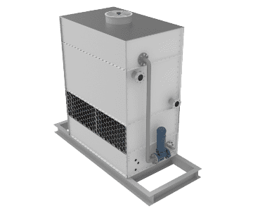
Open Circuit Cooling Towers
Open circuit cooler is a cooling device that achieves process water cooling by spraying the water on the packing and undertaking heat transfer with the air.
Go to Open Circuit Cooling Towers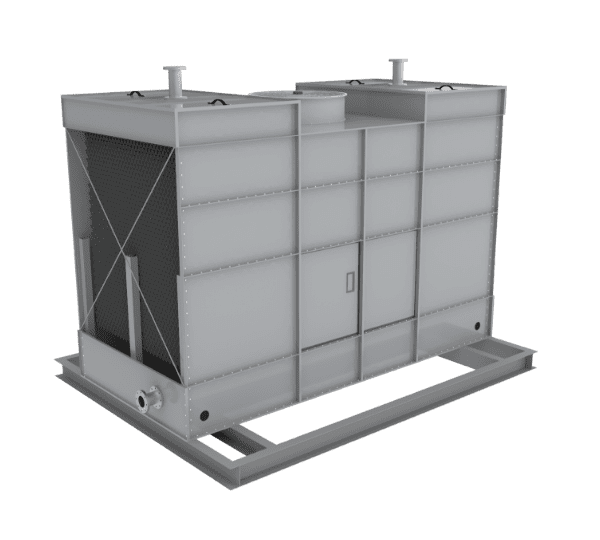
Hybrid Wet Dry Cooling Tower
Hybrid wet dry cooling tower can control the automatic start and stop of the spray pump system to realize a high efficient and energy saving cooling process.
Go to Hybrid Wet Dry Cooling Tower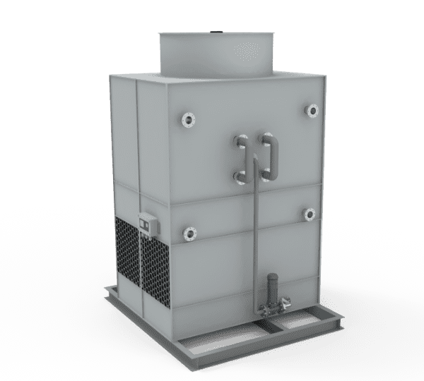
Air Cooled Heat Exchangers
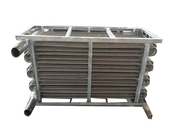
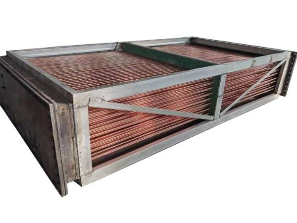
Air cooled heat exchanger is a device that takes air as the cooling medium to cool or condense the fluid in the finned tubes.
Go to Air Cooled Heat Exchangers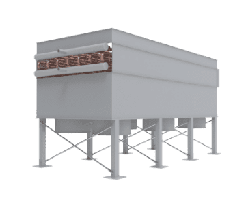
Cooling Tower Fans
Cooling tower fan is mainly used to drive air flow through the cooling tower, thereby facilitating the water cooling in the cooling process.
Go to Cooling Tower Fans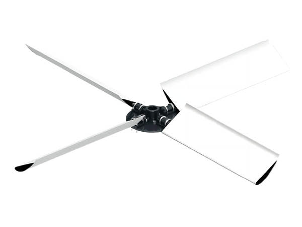
Cooling Tower Gearboxes
Cooling tower gearbox controls the airflow and speed within the cooling tower by adjusting the fan speed, thereby effectively improving cooling efficiency.
Go to Cooling Tower Gearboxes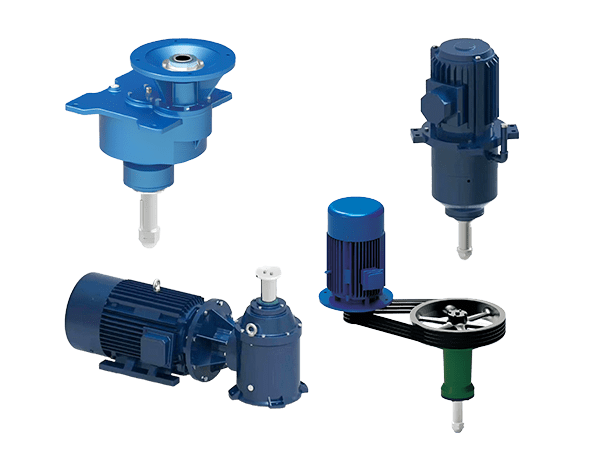
-
Services Services
- Order Information & Selection Guide
- FAQs
- Maintenance Guide
- Videos
- Catalog
- Exploded View Drawing
Order Information & Selection Guide
Our order information & selection guide can help you choose cooling towers perfectly suitable for your application and get an accurate price quickly.
Go to Order Information & Selection Guide
Feiyu Cooling Tower Catalogue
Click for detailed cooling tower technical data & maintenance guide.
DownloadsFAQs
We collect some frequently asked questions about cooling towers to help you better understand our products and place your order quickly.
Go to FAQs
Feiyu Cooling Tower Catalogue
Click for detailed cooling tower technical data & maintenance guide.
DownloadsMaintenance Guide
Refer to the cooling tower maintenance guide can help your cooling tower run smoothly and enjoy a long service life.
Go to Maintenance Guide
Feiyu Cooling Tower Catalogue
Click for detailed cooling tower technical data & maintenance guide.
DownloadsVideos
Our cooling tower videos show our cooling tower types, structures and details. Through this vivid video, you can know more about our cooling tower devices.
Go to Videos
Feiyu Cooling Tower Catalogue
Click for detailed cooling tower technical data & maintenance guide.
DownloadsCatalog
We post our cooling tower product catalog here to help you get detailed production description, data, working principle and structure information.
Go to Catalog
Feiyu Cooling Tower Catalogue
Click for detailed cooling tower technical data & maintenance guide.
DownloadsExploded View Drawing
We offer a full range of cooling tower exploded view drawings to help you get a more detailed understanding of the various types of cooling tower structure.
Go to Exploded View Drawing
Feiyu Cooling Tower Catalogue
Click for detailed cooling tower technical data & maintenance guide.
Downloads - Technology
-
About Us About Us
- Development Course
- Our Culture
- Our Capacity
- Quality Control
- Our Projects
- Applications
Development Course
It briefly introduces our development course from the improvement of manufacturing technology, the introduction of new devices, the development of new products.
Go to Development Course
Feiyu Cooling Tower Catalogue
Click for detailed cooling tower technical data & maintenance guide.
DownloadsOur Culture
We aim to be an industry-leading cooling tower manufacturer & supplier and provide our customers with quality products and professional services.
Go to Our Culture
Feiyu Cooling Tower Catalogue
Click for detailed cooling tower technical data & maintenance guide.
DownloadsOur Capacity
As a leading cooling tower manufacturer, we have advanced equipment, skilled workers and high output capacity to meet our customers' demands for urgent orders.
Go to Our Capacity
Feiyu Cooling Tower Catalogue
Click for detailed cooling tower technical data & maintenance guide.
DownloadsQuality Control
We have established a strict quality control system before, during and after cooling tower production. All products must be qualified before leaving the factory
Go to Quality Control
Feiyu Cooling Tower Catalogue
Click for detailed cooling tower technical data & maintenance guide.
DownloadsOur Projects
Our cooling towers & accessories are exported to all over the world and are highly recognized by local customers. Let's get close to our latest projects.
Go to Our Projects
Feiyu Cooling Tower Catalogue
Click for detailed cooling tower technical data & maintenance guide.
DownloadsApplications
Cooling towers are widely used for cooling the main equipment of steel, manufacturing, new energy, HAVC system, petroleum, textile and other industries.
Go to Applications
Feiyu Cooling Tower Catalogue
Click for detailed cooling tower technical data & maintenance guide.
Downloads - Contact
Closed Circuit Cooling Towers
Counter Flow Cooling Tower with Opposite Spray Water & Air Inlet Flows
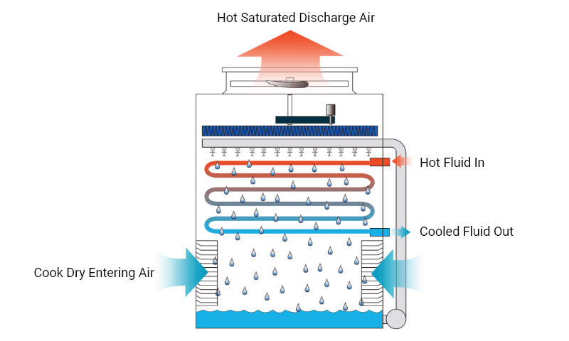
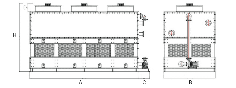
Counter flow cooling tower is a cooling device that is designed to remove the heat of the process fluid, thereby cooling the process fluid. With coil exchangers placed in the tower, the whole cooling process is achieved through heat change among the air, spray water & circulating water via coil exchanger inside.
In the counter flow closed circuit cooling tower, the air is introduced at the bottom of the tower and flows from bottom to top, in the opposite direction of spray water, therefore, it is named as counter flow cooling tower. It is widely used in industrial refrigeration, commercial air conditioning, process processing, district cooling, power industry, etc.
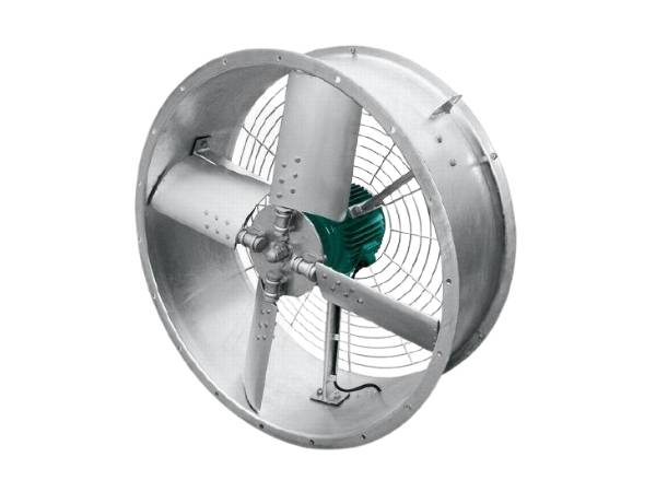
Fan is a mechanical device that is used to increase the air pressure in the cooling tower and discharge the air out. There are two types of fans for counter flow closed circuit cooling tower. One is forced draft fan and the other is induced-draft axial fan. Closed circuit cooling tower with a low height generally adopts a forced shaft fan and is suitable for indoor installation and air duct installation. It is your ideal choice for precise replacement projects.


